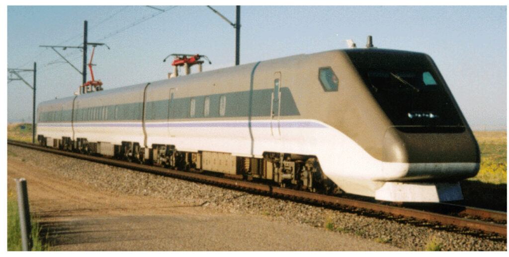
The GCT01 seen at the Transportation Technology Center in Pueblo, CO – Very few photographs remain of the GCT01 in Pueblo
Copyright: USDOT FRA – Public Domain
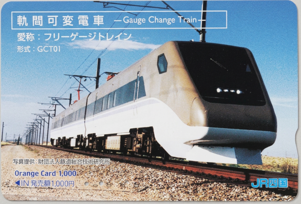
The Japanese Variable Gauge Train, officially known as the Gauge Change Train (GCT) stands out as a unique undertaking in the history of Japanese railroad engineering. The idea of enabling continuous passenger train service between the standard gauge Shinkansen network and the conventional narrow gauge network garnered great interest from the public as well as policy makers in Japan. However, realizing this ambition meant reinventing, reengineering and reevaluating core components that are all extremely safety sensitive, such as wheels, axles, and motors. The project involved numerous unknowns beyond the scope of conventional railroad development that could not be satisfactorily tested and evaluated in Japan.
In order to conduct such intensive testing in a safe, controlled manner, the Railway Technical Research Institute (RTRI) looked to America for help. For two years, between 1999 and 2001, high-speed endurance running tests were carried out at the Transportation Technology Center (TTC) in Pueblo, Colorado. It was unprecedented for a Japanese railcar intended for domestic use in Japan, especially an experimental train showcasing the latest advanced technology, to undergo in-depth testing outside Japan.
Behind those tests lay far more than what published materials alone reveal: the dedication and professionalism of the teams involved, the accumulation of data through trial and error, and close cooperation between Japanese and American engineers and researchers. In this article, Mr. Kazuhiro Oda, who was deeply involved in the GCT project took us back in detail through his career from his first getting hired at Japanese National Railways (JNR), to his work at RTRI, and ultimately to the GCT testing in the United States.


Location of the Transportation Technology Center in Pueblo, CO
Copyright: USDOT – Public Domain
Introduction
Track gauge
Track gauge refers to the distance between the inside faces of the two rails. Standard gauge (used in the US, Europe, China, and to a limited extent in Japan) means 4 feet 8.5 inches (1435 mm), while narrow gauge refers to any gauge narrower than that. The most widely used gauge in Japan is 3 feet 6 inches (1067 mm). This became the standard because the first railroad laid in Japan (under the technical guidance of Britain) in 1872 was built to the colonial narrow-gauge standard.
Narrow gauge trains are generally smaller and slower compared to their standard gauge counterparts. As the railroad network in Japan grew, narrow gauge became an achilles heel, preventing Japan from operating trains at speeds comparable to Europe or America. By the end of the 19th century, momentum had grown for converting Japan’s narrow gauge network to standard gauge. However, this push was met with resistance from those who wanted to prioritize expanding the rail network over a costly track gauge conversion process. Although the matter was debated at the highest levels of the Japanese government, the regauging plan was ultimately canceled.
Japan’s narrow-gauge railway network eventually came to suffer from chronic capacity shortages. To solve this problem, plans were drawn up in the 1930s for a high-speed new standard-gauge line, the so-called “Bullet Train” initiative, and construction actually began in 1939. Although the project was left unfinished and abandoned towards the end of WWII, the land acquired and tunnels dug later became the foundation of the Shinkansen, the modern standard-gauge high-speed rail line we know today.
However, because different gauges were adopted for the Shinkansen vs the pre-existing conventional lines, through service became impossible, forcing passengers to transfer at major stations to continue to their destinations beyond the limits of the Shinkansen network. Compared with the high-speed rail networks of Europe and China, where existing lines and high-speed new lines can operate seamlessly with each other, Japan’s Shinkansen gave users an inflexible impression. In the 1990s, small segments of the narrow gauge network were converted to standard gauge to allow through operation with the Shinkansen. This initiative was known as “mini-Shinkansen”, but the fragmentation of the narrow gauge network emerged as an obvious drawback, and no new mini-Shinkansen projects have advanced since. Outside of Japan, a small number of variable gauge passenger trains do exist. Variable gauge trains have been in revenue service in Spain for decades, but for various reasons, such as the fact that Spain uses broad gauge rather than narrow gauge, they do not suit the unique needs of the Japanese railway network.
That was the background to the GCT. Development began with the goal of creating a high-speed train that could travel on both the conventional narrow-gauge network and the standard-gauge Shinkansen lines.
The preceding section was prepared by the JATHO editorial team as introductory context. What follows is Mr. Oda’s own recollection, presented as faithfully as possible to the tone and nuance of his original narrative. Aside from minor edits and organizational adjustments by the JATHO editorial team, the content is based on Mr. Oda’s emails.
First, my background
Let me begin with my career and where I studied.
I was born in 1952 and am now 74 years old. I graduated with an Aeronautical Engineering Degree from the University of Tokyo in 1975, and joined JNR (Japanese National Railways) the same year. During the 12 years before JNR was broken up and privatized, I gained hands-on experience in rolling stock maintenance across Japan. I worked at four different workshops, from Kyushu to Hokkaido, dealing with locomotives, EMUs (Electric Multiple Units), DMUs (Diesel Multiple Units), and freight cars.
When JNR was broken up into private sector regional passenger operators and an R&D sector, I elected to join the R&D sector known as the Railway Technology Research Institute, or RTRI. At RTRI, I joined the Maglev development team. I was directly involved in car body weight reduction and the development of wheel-based running gear. However, during an experiment on the rubber-tire run flat detection system I was leading, a fire broke out that destroyed the test car. Although nobody was hurt, I was removed from Maglev development and transferred to the conventional railway division. Around that same time, responsibility for Maglev development was gradually shifting from RTRI to JR Central.
By then, basic research on the concept of variable-gauge EMU, officially known as the GCT (Gauge Change Train) was already ongoing under the guidance of various technical leaders. I joined the project partway through, at just the point when development needed stronger cooperation from the Japanese government and the various JRs (private sector regional passenger rail operators) in order to move from research toward practical application. I was involved through support for the endurance testing of the first prototype train (GCT01). After that, the lead role in development shifted from RTRI to the GCT Development Consortium, while I stayed at RTRI and went on to lead the safety assessment project for the Taiwan High Speed Rail. That was when I stepped away from GCT development.
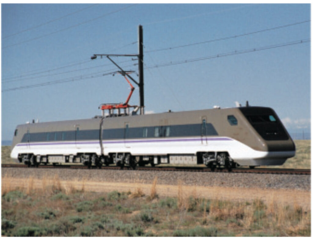
GCT01 as a two-car consist with a strikingly large American pantograph supplied by TransTech – Only running tests were conducted; track gauge changes followed later.
Copyright: USDOT FRA – Public Domain
Why America—and why Colorado?
In short, we took the GCT01 to the United States because we wanted to conduct practical, near-real-world testing that could not be done in Japan.
On an ordinary railway vehicle, the left and right steel wheels are press-fitted onto the ends of the same axle, and they rotate completely in sync. That simple wheelset is one of the most basic and important components in the entire rail car: it supports the weight of the carbody, controls vertical loads, and prevents the wheels from leaving the rails by controlling lateral loads. For propulsion, rotational force is applied to the axle, and the resulting friction between wheel and rail transmits the tractive force.
The GCT under development at the time was completely different. Its wheels were not fixed to the axle; they were independent wheels that could move sideways to change gauge. At the same time, motors were directly connected to those wheels, using a direct-drive motor (DDM) arrangement to deliver power straight to the wheels.
Because the GCT’s target technologies involved the wheels, axles, and motors—parts directly tied to the core safety of the rail car—we followed a rigorous testing process outlined below.
1. Proof of concept: Design and Prototyping of the Core Components
At this early stage, we focused on the core development elements.
For the GCT, the first step was to confirm two things: whether the spacing between the left and right wheels could be safely changed to match the track gauge of the track below, and whether a system using independently driven left and right wheels would function properly. To do that, we built trucks and tested it by having a separate vehicle pull it through the Gauge-Changing Equipment (GCE), the specially engineered track section where the rails transitioned from narrow gauge to standard gauge.
Our goal was to create an Electric Multiple Unit (EMU), as opposed to locomotive drawn carriages, so we needed powered cars whose trucks could change wheel gauge. But during the gauge-change process, the wheels are lifted from the rails while they transition laterally, so no tractive force can be transmitted to the track. In that phase, the vehicle is effectively operating as an unpowered trailer car. That is why proof-of-principle testing of the gauge-changing process was done in tow. At the end of RTRI’s existing loop track in Tokyo, we built a GCE accompanied by rack railway track, like those used on mountain railways, and used a rack locomotive to tow the trucks through the GCE track section.
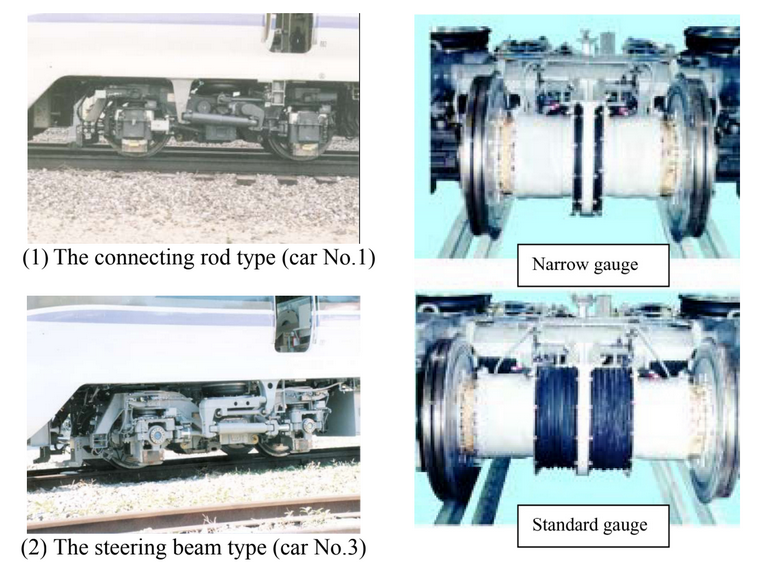
The “A trucks” in both standard gauge and narrow gauge
Copyright: RTRI – Fair Use
2. Track gauge Conversions in both Unpowered and Powered Mode
A truck cannot run by itself; it takes a lot more to form a whole, functioning rail car. That meant building not just the mechanical components of the GCT described above, but every system needed for an operating train, including the motor drive system and braking system. To do that, we built the first prototype train (GCT01).
At first, the GCT01 comprised of the smallest possible consist of just two cars. It consisted of two cab cars coupled back to back. Later, during testing at TTC, we added an intermediate car and turned it into a three-car set. For these tests, the GCE was modified so the train could pass through it under its own power and then continue running on RTRI’s narrow-gauge loop test track.
A railway system is made up not just of the train, but also signaling systems, rails, overhead catenary, turnout, and many other related systems. Compatibility between the train and those other systems also had to be verified, but that could not be done on RTRI’s Test track. Issues did come up from real world testing outside of RTRI, such as for train-position detection, which is essential to control a signaling system. That became one of the reasons for developing an improved GCT design with a revised drive system.
3. Confirming Compatibility with Existing Railway Infrastructure
In order to validate the GCT’s compatibility with existing railroad infrastructure, equipment and systems, the GCT needed to be tested on JR lines, even for a brief period. The GCT needed running tests on both conventional narrow-gauge lines and standard-gauge Shinkansen lines.
Step 1
JR West was kind enough to close down a small section of their narrow gauge network (the Sanin Line) after midnight, outside of their operating hours, to help us facilitate nighttime running tests. Building on what we already knew from our earlier onsite testing at RTRI, we increased speed gradually and confirmed safe narrow-gauge operations at speeds up to 100 km/h (62.1 MPH), the maximum speed permitted under the track geometry and conditions. Personnel were posted at every level crossing in the closed track section, and Maintenance of Way (MoW) and electrical power personnel were also kept on standby in case of any trouble. Due to the highly experimental nature of the GCT, only with that level of readiness could the tests be carried out.
Step 2
Because the goal of the GCT was to operate on standard-gauge Shinkansen lines, we also had to prove that it could run safely at 250 km/h (155 MPH) in Shinkansen territory. But that required far more preparation than testing on the conventional narrow-gauge lines. The GCT and our test team needed to show a strong record of safety and reliability before we could use the active High-Speed-Rail infrastructure of the Shinkansen, the economic lifeline of Japan, for our tests.
That meant we needed to find a dedicated standard-gauge test line, one where testing could be done day and night. Japan simply had no dedicated test facility where a prototype rail car could be freely tested, and using portions of the existing railway network for our tests came with too many restrictions.
4. Using the TTC test track in Pueblo, Colorado
That is when the idea emerged to use the Transportation Technology Center (TTC) in Pueblo, Colorado. The plan was to use the American test track to conduct progressive speed build-up testing and endurance testing.
Step 3: Speed-increase testing of GCT
We reached a top speed of 246 km/h (152 MPH).
Step 4: Endurance testing of GCT
We accumulated about 600,000 km (372,000 miles) of running distance. During that time, we also overhauled the trucks, which allowed us to identify any potential weak points in maintenance, detect potential abnormal wear in components, and check for any deterioration in vehicle performance.
Only after building that record were we finally able to bring the first GCT test train back to Japan and prepare for progressive speed build-up testing on Shinkansen lines and endurance testing on narrow-gauge conventional lines. To reiterate the key point: in Japan, without a dedicated test line, high-speed standard-gauge endurance testing simply was not feasible.
As a side note, endurance testing on actual Shinkansen lines has unfortunately still not been carried out.
Working with the Americans
My interactions with the Americans as we launched testing in the United States were as follows.
Working with the FRA
The TTC is Federal property owned by the Federal Railroad Administration (FRA), but the facility was operated by a private sector operator known as the Transportation Technology Center Inc. (TTCI). The FRA had a resident liaison stationed at TTC, and he would communicate with FRA HQ in Washington, DC as needed. As a result, during the two-year test period, there were only two direct contacts between RTRI and FRA HQ in Washington. On both occasions I travelled to Washington, DC and reported directly to the head of the FRA’s research division on the progress of our testing. From preparation through completion, everything else proceeded smoothly onsite at TTC.
Correspondence with TTCI
Because of its geography as a continental nation, the United States is a railroad empire dominated by freight railroads. TTC, the testing facility, was therefore operated by TTCI, a private company which is a 100% subsidiary of the Association of American Railroads (AAR). TTCI mainly handled product testing for AAR members, but it was also their policy to expand business beyond the AAR membership. As long as the client paid the testing costs, TTCI was willing to undertake testing regardless of whether the customer was American or foreign. You could say America felt more open back then.
Around the same time as the GCT tests, the TTC was also being used to test the first generation Amtrak Acela: the train that later entered service in 2000 on the Northeast Corridor between Boston, New York and Washington, DC at a maximum speed of 150 MPH. For TTCI, testing passenger trains was as familiar a task as testing freight trains.
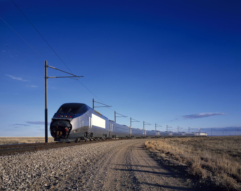
The Amtrak Acela underwent performance verification testing in Pueblo at the same time as the GCT01.
Copyright: USDOT – Public Domain
First visit to the TTC
The first discussions and site visit to determine whether GCT endurance testing could be carried out at TTC took place in September 1995. Four of us travelled from Japan for the first time: one executive from the rolling stock side, one planner, and two engineers—one responsible for the gauge-changing mechanism and one for the Direct-Drive Motor of the wheels. We flew Narita to Los Angeles to Denver to Pueblo, transferring to smaller and smaller planes each time, and by the end we were battling motion sickness on a small propeller plane with seating for maybe 40 passengers.
Once the tests began and we became more experienced travelers, we settled on a better route: fly into Colorado Springs on a large jet and drive the remaining hour or so. But of course we had no way of knowing that at the time. As for hotels, the Holiday Inn was considered the premium choice. By the time testing concluded, a Marriott had opened, but when we first arrived we really felt we had come to the middle of nowhere. It was the kind of town where people joked about the “traffic jam” if two cars happened to stop at a red light.
For our first visit, a representative from TTCI met us and drove us from the hotel, but after passing the outskirts of town and the airfield, and even after passing the last sign for TTC, the road just kept going and going. People visiting the TTC for the first time without being picked up, often think they’ve gotten lost and turn back, because there is simply nothing along the road before you finally reach the TTC gate. The TTC site is so large that Tokyo’s Yamanote Line loop would fit inside it. To our surprise, armed guards carrying rifles stood watch at the gate. We were told this was required for federal facilities. This was still before 9/11, so security was not yet as strict as it became later, but the place already had an imposing atmosphere.
The armed guards at the gate made me nervous, but once we got inside and the first meeting began, we were treated very warmly, and at that moment I felt confident that we could carry the tests successfully through to the end. It made me realize that railroad professionals, whatever country they come from, share a certain atmosphere. The Americans there even said “We smell the same”. In Japan we speak of a “railway family”; in America they call it a “railroad fraternity”, you could say it’s the same idea.
We explained the technical details and the overall two-year plan, and because they too were a research organization, they were very easy to communicate with. They even encouraged us by telling us “Precisely because there are risks, our test track is in the middle of nowhere where it doesn’t matter what happens.” Our goals were certainly challenging, but I was confident it was not that dangerous a test, and TTCI’s attitude reassured us. TTC’s facilities were all standard gauge and designed for axle loads up to 30 tons. The curves were tighter than I expected, but Acela testing had already demonstrated that speeds of 150 MPH were manageable.
The two planning staff at TTCI who worked with us then remained supportive of the GCT tests all the way through. Twenty-six years later they have both retired and moved away from Pueblo, but we are still friends to this day.
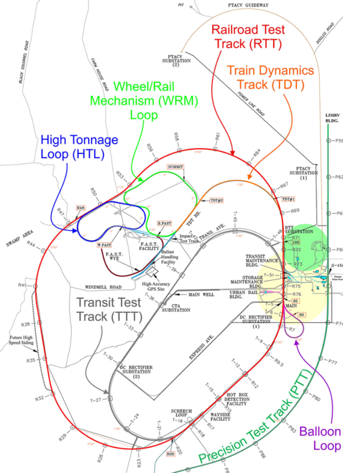
The full scope of the Transportation Technology Center (TTC) – Most of the GCT tests were conducted on the Railroad Test Track (RTT)
Copyright: USDOT – Public Domain
Building dedicated GCT facilities
If all the GCT had to do was to run, then all we had to do was send it endlessly around the 13.5 mile standard-gauge Railroad-Test-Track (RTT). But the GCT also had to demonstrate repeated gauge changes during these tests. And the purpose of the endurance test was not just to keep the train running, it was also to verify whether GCT performance could be maintained under the same periodic inspection rules used for Japanese rolling stock. If the gauge-changing mechanism was so complicated and sensitive that it demanded excessive inspection and maintenance, it would not be practical.
So one objective was to prove that the train could be safely maintained only with the inspection schedule used in Japan: routine inspections every three days, and periodic inspections every sixty days, with no extra maintenance beyond that. The TTC did have heavy equipment onsite that was capable of disassembling and inspecting rail cars, equivalent to what we would classify as “General overhauls” in Japan, but we could not occupy those facilities continuously every three days for two years. That would interfere with TTC’s other commitments. And the TTC had no narrow-gauge track at all.
So we decided to build additional facilities: a dedicated GCT maintenance shed, a set of Gauge Change Equipment (GCE), and 300 meters (984ft) of narrow-gauge track beyond it. This was a major construction project involving civil works. There were two possible layouts.
Plan A: Add a new turnout from the Railroad Test Track (RTT), pass through the GCE to a narrow-gauge line running alongside the loop, then pass through another GCE to return to standard gauge and rejoin the loop through another turnout.
Plan B: Place the dedicated maintenance facility, GCE, and narrow-gauge track all in a straight line off the RTT, with the narrow-gauge line ending as a dead-end siding. This would avoid affecting the RTT itself.
In negotiating cost sharing with TTCI, we tried to minimize our financial burden by offering conditions that would allow the TTCI to reuse the facilities after GCT testing concluded by converting the tracks to standard gauge. As a result, we chose Plan B. TTCI also preferred not to add additional turnouts to the Railroad-Test-Track (RTT), apart from the one needed for access. After all, turnouts are maintenance-intensive and can impose speed restrictions. Another advantage of Plan B was that we could add components in stages as the testing progressed. The vehicle maintenance shed was needed from the beginning, but the GCE and the narrow-gauge track beyond it could wait until testing had stabilized enough that the risk of interruption from unknown problems would be lower.
As planned, once GCT testing was stable, the GCE and narrow-gauge section were completed within a year. The GCT maintenance shed and associated facilities were named the “Japan Rail Facility”. As a side note, after GCT testing concluded, the GCE was cut up into 4” segments and discarded to protect proprietary information, and the narrow-gauge track was converted by TTCI into standard gauge, extended, and put to effective use. Today the facility is called the “Joint Research Facility”, a fitting name commemorating the joint efforts of the GCT tests. Its nickname was, and still is, “JR House.”
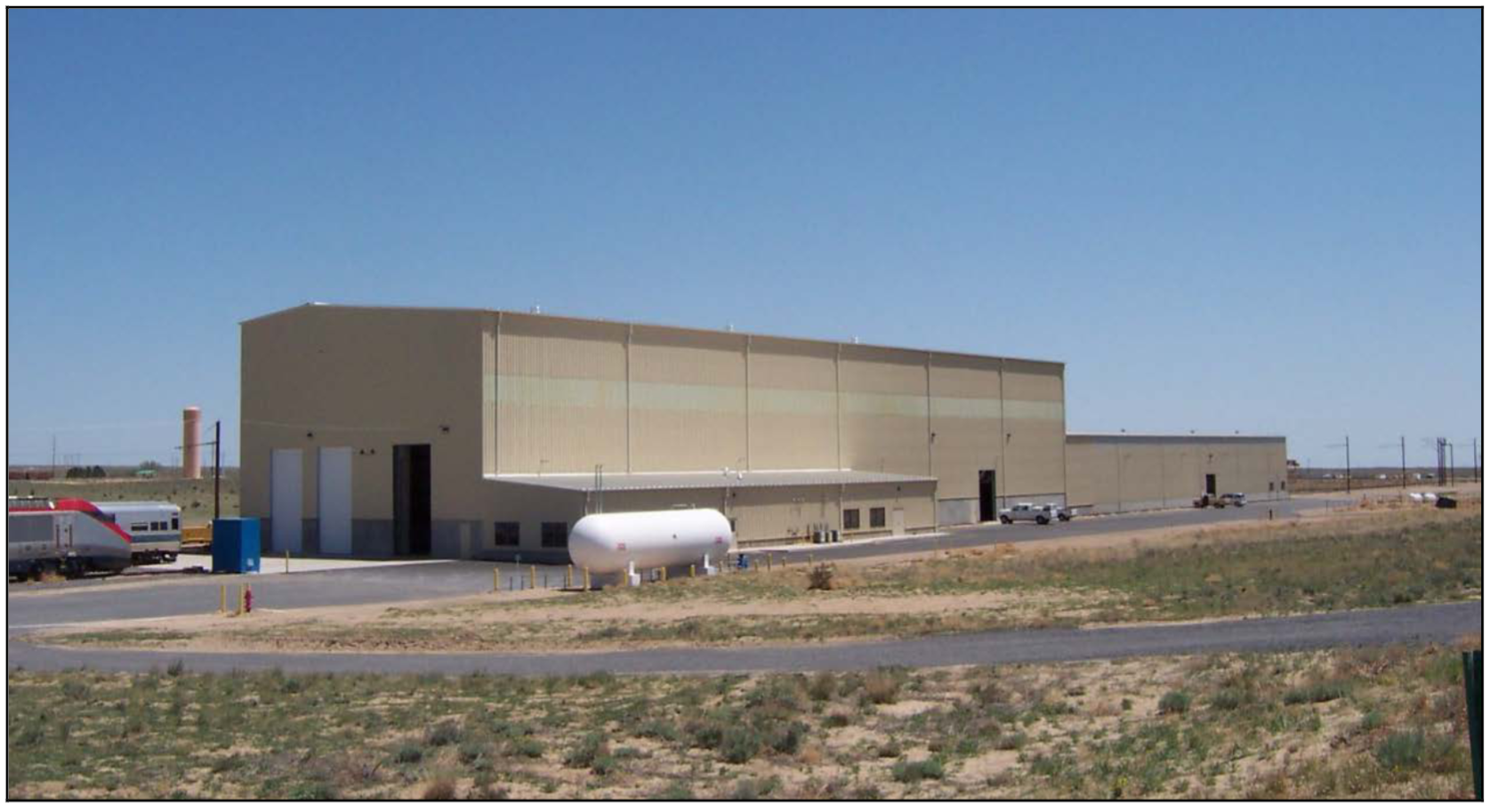
The Japan Rail Facility, known as “JR House,” which was later expanded and is still in use today.
Copyright: USDOT – Public Domain
Training TTCI maintenance staff
During the endurance tests, we wanted to maintain the same inspection schedule in the U.S. that we used in Japan. But it would have been inefficient to station all necessary maintenance personnel from Japan. For certain test phases, such as progressive speed build-up testing or truck teardown inspections, we did dispatch groups of researchers from Japan for short periods. But for routine inspections, we decided to entrust the work to TTCI employees.
To make that possible, TTCI technical staff were brought to Japan and trained. After several rounds of onsite discussions and studies of TTCI’s operations and facilities, and after observing the Acela tests, we determined that their capabilities were fully sufficient for our needs.
The first phase of training took place when the GCT01 train was towed from the manufacturer to RTRI and preparations were being made for self-propelled testing onsite. That work was similar to what would later be required in the US: reassembling the car body and trucks after the train had been disassembled for transport to TTC and restoring it to operable condition. In that sense, the training also served as a rehearsal for vehicle assembly in America.
The TTCI technician who came for that first phase of training struck me as a cheerful cowboy, if you will. He was highly proactive, eager to get involved in the work, and full of curiosity. He had grown up in the Midwest and had never traveled to Japan before. For him, using trains in daily life was a completely new concept. Although he worked at a railroad research organization in America, the equipment he usually dealt with was diesel locomotives and freight cars. He embodied the American reality where someone can work in railroad research but have never ridden an electric train as a passenger in real life. The nearest urban rail system from TTC was Denver’s Light Rail, about three hours drive away. American freight railroads use standard gauge, with double-stack container cars and tri-level Autoracks. To him, accustomed to such massive American trains, the relatively small GCT01 looked “like a toy,” as he put it.
He became a key supporter of the GCT tests campaign at TTC. Far from Japan, where many little replacement parts were extremely hard to find, he somehow managed to track down what we needed. He and his family even invited the visiting Japanese staff to their home and helped ease the difficulties of life in America. His support, in ways both tangible and intangible, was tremendously helpful.
Later, the second type trucks, called “B trucks” were introduced during the second year of endurance testing as a successor to the direct drive motor gauge-changing “A trucks”. Instead of direct wheel drive, they transmitted power through the axle. We shipped an intermediate car body to go with the pair of B trucks to TTC and expanded the GCT01 from a two-car consist to a three-car consist. That also led to another round of training in Japan so TTCI staff could learn truck assembly in advance. In total, seven TTCI field technicians came to Japan for training. In effect, that was like assembling a seven-man Japanese support team, and their work at TTC became a major factor in achieving success in our testing.
After the tests were over, we used airline miles accumulated by RTRI staff on business trips to invite the first of those maintenance technicians to Japan. That time he came not for work, but with his wife, and they enjoyed railway travel all around Japan.
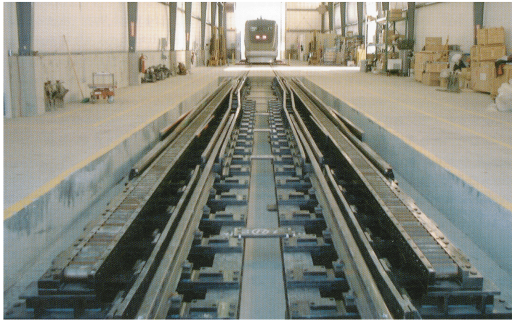
The Gauge Change Equipment (GCE) inside the Japan Rail Facility
Copyright: USDOT FRA – Public Domain
American technology and standards
Japanese railroads are based on Japan Industrial Standards (JIS), while American railroads are based on American Association of Railroads (AAR) standards. There are many differences between the two, but the first issue for us was the wheel tread profile.
For a train to run safely, the relationship between wheel and rail shape is crucial. If a wheelset shifts sideways while rotating due to centrifugal force, cant, or some other force, the difference in effective diameter between the left and right wheels changes, producing a restoring force that brings the wheelset back toward center. If that restoring force is appropriate, it helps the vehicle pass through curves smoothly. However, if it is too strong or too weak, it can actually worsen stability. Generally speaking, a strong restoring force is helpful at low speeds but can become destabilizing at high speeds.
The GCT01 had been designed so that the wheel-rail relationship would remain stable both on low-speed conventional narrow gauge lines and high-speed standard gauge Shinkansen lines, all based on JIS standards. In the United States, however, the rails and wheels followed AAR standards. So if we had simply brought the GCT over as-is, we would have been combining JIS wheels with AAR rails. That would change how the wheels behaved when it shifted laterally. For that reason, we had to study how to alter the GCT wheel profile so that running on AAR rails would produce behavior equivalent to running on Japanese JIS rails.
Example of wheel profile interacting with rail profile
Copyright: APTA – Fair Use
Is bigger always better?
Japanese and American railroads also differ in rolling stock profile (loading gauge) and structure gauge, but the GCT01’s relatively small dimensions were all within the U.S. limits, so that posed no problem. Axle loads differed even more. The American standard was up to 35 tons per axle, while the GCT was only 13 tons, so it was well within the American allowance. In many respects, America’s larger, heavier standards accommodated the smaller Japanese ones without any issues.
But the turnouts on the Railroad Test Track (RTT) were a different matter. The turnouts used at TTC were a simple, low-maintenance design with deliberate gaps in parts where the wheel flange passes through. Large, heavy American rail cars could withstand the impact of passing through those gaps even at high speed, so that simple design was acceptable for them.
Japanese JIS wheels and American AAR wheels differ in width. American wheels are thicker to handle heavier axle loads. Because American turnouts are designed for those thicker wheels, if a thinner Japanese wheel passed through them, the gap is excessive. There is too much wiggle room. That means greater impact forces on the wheel. The GCT was a lightweight, comparatively delicate vehicle, so those impacts would have been greater than what it had been designed to withstand.
So we imported a movable-point frog turnout (aka Swingnose crossing turnout) from Japan—a design whose nose closes tightly and eliminates the gap, and which is commonly used on Japanese high-speed lines, and replaced the original American turnout. That allowed us to create Japan-like conditions for the endurance tests. This was a case where “big” American standards did not fully cover “small” Japanese ones.
American standards in Japan
There were also standards that worked perfectly between the two countries. One example was the automatic coupler used in switching operations, which we needed in order to move the GCT around the TTC with their locomotive.
Even though the GCT was an EMU, it would occasionally need to be coupled to a locomotive, so it carried dual-purpose couplers. On one side it had a tight-lock coupler for coupling with other EMUs; on the reverse side, rotated 180 degrees, it had a locomotive-style automatic coupler. That automatic coupler could be used with American locomotives exactly as it was brought from Japan, because Japanese and American automatic couplers have identical shapes and dimensions. Even the coupler height matched perfectly.
The reason for this commonality is rooted in history. In the early years of Japanese railroads, numerous mutually incompatible coupler types were in use. When Japan eventually standardized them all at once, the American automatic coupler was adopted as the common standard, and that design has continued in service ever since. It was one of those moments when we felt a sense of closeness with American railroading.
The automatic couplers commonly used on locomotives and freight cars on Japan’s conventional railway lines are actually based on American standards.
Copyright: TK14 – Fair Use
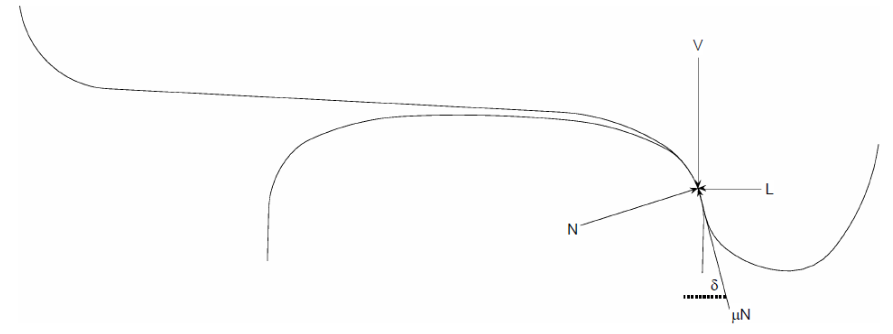
TTCI’s running safety criteria
The criteria for judging running safety were essentially the same in Japan and the US. In both countries, the Derailment Coefficient (Q/P ratio): the ratio of lateral force on a wheel to vertical force, is measured and compared against a critical value based on the Nadal formula. If the Derailment Coefficient remains above that critical value for a designated length of duration, it is deemed unsafe.
The difference was in how the length of duration was defined and measured. We in Japan defined the duration as a function of time (20 milliseconds or more) whereas the TTCI measured travel distance (equivalent to three consecutive wheel revolutions) rather than time. At 150 km/h (93 MPH), three wheel revolutions correspond almost exactly to 20 milliseconds, so the two standards were nearly equivalent. At 250 km/h (155 MPH), incidentally, a wheel would rotate five times during Japan’s 20 millisecond measurement window.
During the progressive speed build-up tests, the TTCI monitored the same Japanese time-based derailment-coefficient waveforms in parallel as part of ensuring the safety of its own staff. After confirming that the train met TTCI’s safety standards and that both the RTRI and TTCI agreed it was safe to do so, we proceeded to increase the speed to the next target.
Hazardous material regulations
In terms of safety culture, I felt a fundamental difference between Japan and the US. American Hazardous Material Regulations were extremely strict. It was mandatory to post highly visible signage and information about the presence of hazardous materials and what to do in an emergency.
This is not to say Japan is careless about hazardous materials. But in Japan, there is a deeply rooted assumption that air and water are safe, and that safety in general is a given. People live and work in an environment safe enough that they need not constantly worry about hazardous materials. Particularly in workplaces, the American approach seemed to be to allow hazardous materials for the sake of practicality, but properly warn people about them. In Japan, the cultural norm is to aim for an environment completely free of hazardous materials in the first place, even if that makes work less convenient.
We, the Japanese engineers and researchers, took for granted that rail cars, being tools used by the general public, are naturally free of harmful substances, and therefore even our workplace was generally assumed to be safe. That is why it came as a surprise to us when the Americans demanded documented proof that the oils, greases, and wear dust generated during our tests were harmless. Fortunately, and really, unsurprisingly, the materials used in railroads are largely identical between Japan and the US, so the equipment and materials we brought all had equivalent counterparts onsite at the TTC. Consequently the explanation to TTCI and the required safety certification went smoothly.
Dealing with US Customs
This story is about how the B truck had to be shipped from Japan in the middle of the GCT running test. Because we only had a two year window scheduled for the test campaign, the schedule was tight and materials had to arrive on time. But the expected arrival date for the B trucks came and went, and there was no sign of those promised B trucks. We were irritated and muttering that America was careless and sloppy compared with Japan, where everything runs on time.
It later turned out, though, that the shipment had been held up in customs. The B truck’s special axle had been mistaken for the barrel of an artillery cannon. The axle had been machined so that the wheels could move laterally, but the grooves apparently looked like the rifling inside a gun barrel, leading customs officials to suspect weapons smuggling. With support from TTCI, we explained the situation to US customs, and although the delivery was delayed, it arrived safely. The experience reminded us that America is in fact not careless, it is simply very strict when it comes to security.
The wildlife
We had our fair share of issues involving the local wildlife. TTC sits out in open country and is home to many wild animals, including dangerous rattlesnakes.
Because snakes are cold-blooded, they are highly sensitive to ambient temperature. During the summer, the ambient temperature in Pueblo can approach 40°C (104°F) under the blazing sun. Under those conditions, the steel rails inside the maintenance shed, being the only roofed place out there, felt pleasantly cool to the touch. What feels good to a person feels good to a snake too, so the rails in the shed became an ideal summer refuge for snakes. During summer, rattlesnakes were found several times coiled comfortably on the tracks inside the shed. We had been warned in advance, but they still startled Japanese engineers and researchers inspecting the undersides of the GCT more than once. No one was actually hurt, but of course TTC kept antivenom on hand just in case.
Rattlesnakes just emerging from hibernation in spring were also problematic. At that time of year, the air is still not warm enough for them to be fully active, so they need to warm up. They do that by basking on the black asphalt roads, which absorb sunlight and become warmer than the surrounding ground. When many rattlesnakes emerge at once, you can see them coiled in the road, or dead in large numbers after being run over by commuting cars. It’s a surreal sight, but it’s obviously a bad idea to step out of the car to get a closer look.
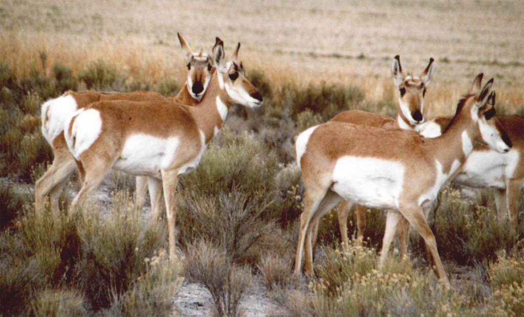
Collisions with pronghorns became an unexpected headache for the testing of the GCT
Copyright: Rvannatta – CC BY-SA 3.0
The pronghorn antelope were another source of headaches. They are small hoofed mammals that look a bit like deer, and they live in the vicinity of the TTC in herds. During running tests, when a herd crossed the track, the leading pronghorn would often start across with what seemed like enough distance from the approaching train, and the rest of the herd would blindly follow. This would result in the GCT hitting the pronghorns. Sometimes it was one, sometimes several.
Neither the pronghorns nor the TTCI staff were used to such high-speed trains, so there was no warning about this in advance. The GCT’s nose was made of FRP (fiber reinforced plastic), so a collision could easily damage it, and in the worst case a pronghorn could be dragged into the undercarriage. Then, after returning to the shed, removal, cleaning, disinfecting, and deodorizing became a major undertaking. Wild animals have a very strong odor. To mitigate this, we attached a cowcatcher to the front of the GCT to throw any approaching wildlife clear and prevent them from being pulled underneath, much like the kind you see on locomotives from the Old West.
Pronghorns also collided with cars commuting to TTC at night, especially on snowy winter roads. Drivers were instructed not to swerve or brake sharply to avoid them, since that was actually more dangerous. Instead, they were told to keep going straight and take the collision, regardless of potential damage to the car. Any pronghorn remains scattered on the tracks or road were usually cleaned up the same day by coyotes and vultures.
In the latter half of the test runs, the train took the form of a three-car consist equipped with a cowcatcher – not only were running tests conducted, but track gauge changes were also repeated.
Copyright: USDOT – Public Domain
600,000 km (372,000 miles) in two years
Over the two year test campaign, we logged 600,000 km (372,000 miles) of cumulative running distance, which was a difficult figure to achieve. On Japan’s conventional lines, accumulating 600,000 km would have taken five to six years. To do so in only two years, we had to operate at roughly three times that efficiency.
To ensure our success, we set up a three-shift system, eight hours per shift. The first shift ran from 4 p.m. to midnight, with a three-person driving team—two drivers and one observer—keeping the train moving continuously. The second shift, from midnight to 8 a.m., was handled by another three-person team, giving us 16 hours of running time per day and allowing us to keep the odometer running at the highest speeds possible. After that, the GCT returned to its dedicated shed (the Japan Rail Facility), and during the third shift, from 8 a.m. to 4 p.m., it underwent inspection and maintenance, including replacement of worn parts. Then the cycle repeated.
All driving was carried out entirely by TTCI employees. If a problem arose during running, RTRI staff stationed there during the day would instruct TTCI personnel and get the train restored to service as quickly as possible. It was the most efficient possible shift pattern.
At first glance it may seem that daytime testing was the privileged slot, but it really wasn’t for us. If trouble occurred during night running and repairs were needed, TTCI support could begin the next morning immediately. If the train had been running in the daytime instead, repairs could not be carried out at night and we would lose a full 24 hours waiting for the next daytime slot. In that sense, we were actually in a more favorable position than Acela, which was conducting daytime testing at the same time.
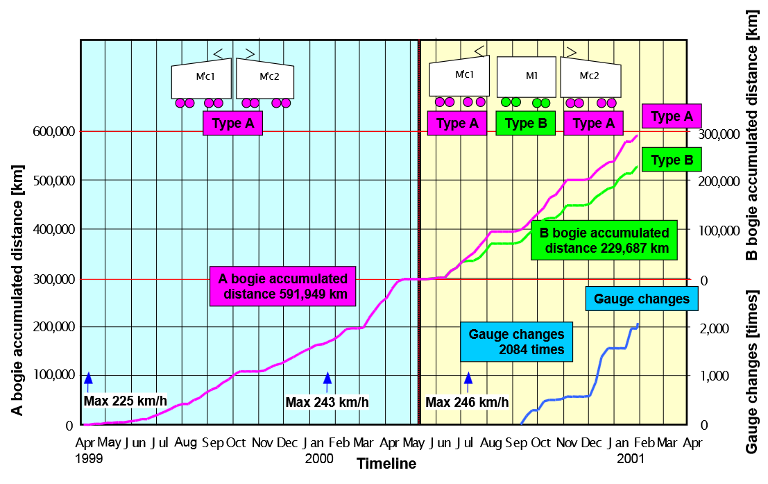
Accumulation of mileage traveled (from Railway Technical Research Institute data)
Copyright: RTRI – Fair Use
RTRI’s resident staff
In the early phase after testing began, we were unfamiliar with the work and also hampered by the time difference with Japan, which made decision making a time consuming affair. As a result, we were not logging mileage at the pace we had hoped for.
So partway through the test campaign, we stationed two full-time RTRI representatives on site. In the engineering world, there really is no substitute for face-to-face communication. Their contribution was enormous. Since the test runs took place from evening until morning, emergency calls came during the middle of the night, just when they were trying to relax at home. During the day they supervised GCT inspections and maintenance; at night they had to respond to emergencies. One was a Japanese staff member with some overseas work experience; the other was a Swedish gentleman who spoke and wrote perfect Japanese. He himself experienced a collision with a pronghorn while driving to an emergency nighttime call in snowy weather.
They also handled visitors from Japan. When members of the Japanese Diet visited, they coordinated with the Japanese consulate in Denver and even arranged dinners. They also received delegations of elected leaders from regions in Japan hoping to introduce the GCT, as well as many technical investigators from abroad. I suspect they endured many unseen hardships.
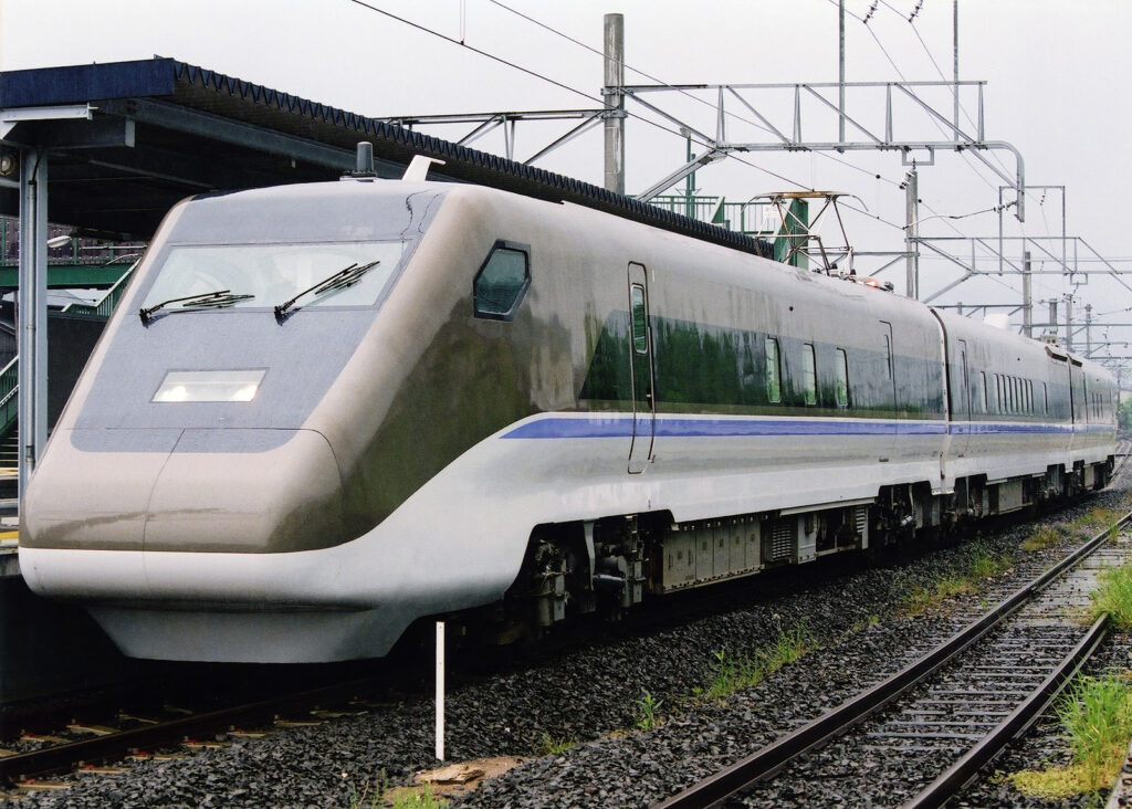
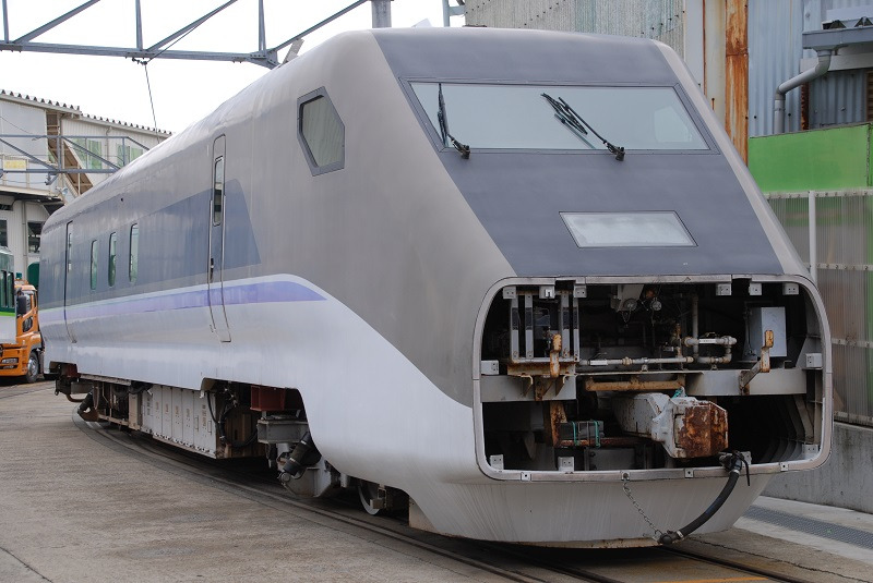
The GCT01, back in Japan to continue testing – note the significantly smaller pantograph and lack of cow catcher
Spaceaero2 – CC-BY SA 3.0
Closing remarks
That concludes the recollections of Kazuhiro Oda concerning the course of the GCT tests in the United States and his experiences on site.
What emerges from his account is that the GCT’s testing at TTC was far more than just another round of overseas trials. It was an unusually ambitious undertaking: Japanese railway technology making use of a foreign test site to push past limits that could not be overcome at home. What sustained that effort was not only institutional support or physical infrastructure, but also the trust built among engineers and researchers as they made decisions in real time to keep the tests moving under tight constraints of time and budget.
The GCT01 was later shipped back to Japan, where testing continued. Second and third generation GCT test trains were subsequently built and put through further trials. In the end, however, the GCT project could not fully resolve issues of maintainability and cost, and as of 2026 the original concept of through service between the Shinkansen and conventional narrow-gauge lines has yet to be realized. Even so, this should not be dismissed simply as a technical failure. Passenger rail services in Japan are operated almost entirely by private-sector businesses, which are highly sensitive to cost. The consequences of that reality later became politicized in debates over projects such as the West Kyushu Shinkansen and other planned Shinkansen lines, which were counting on GCT technology to reach operational status.
What Mr. Oda’s testimony reveals, however, is the historical significance of the testing itself—something that cannot be measured solely by whether the GCT entered revenue service. The record of this test train, running day and night for two years across the Colorado desert, deserves to be remembered as a chapter in the technological history of both Japan and the United States: a story of engineers and researchers from two countries working side by side across barriers of culture and technical standards.
Mr. Oda also noted that a more detailed technical explanation can be found in the May 2003 special issue of RTRI’s periodical RRR, devoted to the GCT. The RTRI archive does indeed list a May 2003 issue of RRR on the development status of gauge-change trains, including an article by Kazuhiro Oda.
Finally, the JATHO editorial team extends its sincere gratitude to Mr. Kazuhiro Oda for taking the time, despite his busy schedule, to share such a long and detailed recollection and to grant permission for its publication.